Difference between revisions of "Mesh Generation for 3D Axisymmetric Problems"
Drrbradford (Talk | contribs) (Created page with "'''Coming soon''' I recently did some work where I need an axisymmetric mesh but a fully 3D solution. I found minimal documentation for this so will write a brief process for it...") |
Drrbradford (Talk | contribs) |
||
| (16 intermediate revisions by the same user not shown) | |||
| Line 1: | Line 1: | ||
| − | + | The following is a brief summary of how to create a three-dimensional axisymmetric mesh. It is based on my limited experience using OF2.0 to build a hemispherical mesh which is then solved with simpleFoam or pisoFoam. This may be of interest for people looking at axisymmetric geometries at non-zero angles of incidence.<br /><br /> | |
| − | + | == Step 1 == | |
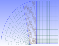
| − | --[[User:Drrbradford|Drrbradford]] | + | Build a quasi two dimensional mesh (i.e. one that is a single cell deep) of the plane which you would like to revolve to form the three dimensional mesh. An example is shown in the first figure. For this mesh, the front and top edges of the domain are defined as the inlet and the rear (rightmost vertical edge) is the outlet. [[File:Screenshot-4.png|200px|thumb|right|Quasi two-dimensional (one cell deep, into screen) mesh which is used for generation of asymmetric domains.]] The axis of symmetry and any internal boundaries don't require specification of boundary types. OpenFOAM should pick up that they are internal boundaries automatically.<br /> |
| + | == Step 2 == | ||
| + | Make sure the front and back faces have different names. Let's call them <front> and <back> for now.<br /> | ||
| + | == Step 3 == | ||
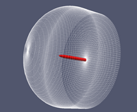
| + | [[File:3D_domain.png|200px|thumb|right|Example of an axisymmetric domain for use with three dimensional flows.]]Now use the extrudeMesh function to sweep the plane to create a hemisphere. To do this type extrudeMesh in the command line just like any other openFOAM application. The options for the extrudeMesh are specified in the extrudeMeshDict file. An example is below. Some important parameters: <br /> | ||
| + | ''nLayers N;'' creates N cells in the azimuthal/circumferential direction. <br /> | ||
| + | ''axisPt (x y z);'' defines a point on the axis of symmetry. <br /> | ||
| + | ''axis (X Y Z);'' defines the vector which is coincident with the axis of symmetry. <br /> | ||
| + | ''angle A;'' sweeps the mesh through A degrees (set to 360 for sully axisymmetric problem).<br /><br /> | ||
| + | <code> | ||
| + | FoamFile<br /> | ||
| + | {<br /> | ||
| + | version 2.0;<br /> | ||
| + | format ascii;<br /> | ||
| + | class dictionary;<br /> | ||
| + | object extrudeMeshDict;<br /> | ||
| + | }<br /><br /> | ||
| + | |||
| + | constructFrom patch;<br /> | ||
| + | sourceCase ;<br /> | ||
| + | sourcePatches (<front>);<br /> | ||
| + | exposedPatchName <back>;<br /> | ||
| + | extrudeModel wedge;<br /> | ||
| + | mergeFaces false;<br /> | ||
| + | nLayers 180;<br /> | ||
| + | expansionRatio 1.0;<br /> | ||
| + | wedgeCoeffs<br /> | ||
| + | {<br /> | ||
| + | axisPt (0.55 0 0);<br /> | ||
| + | axis (1 0 0);<br /> | ||
| + | angle 360; <br /> | ||
| + | }<br /> | ||
| + | </code><br /><br /> | ||
| + | |||
| + | == Step 4 == | ||
| + | Make sure <front> and <back> are defined in initial conditions ~/0/U, p, k etc. <br /> | ||
| + | == Step 5 == | ||
| + | Run the stitchMesh with the perfect option implemented:<br /> | ||
| + | <code>stitchMesh <front> <back> -perfect</code><br /><br /> | ||
| + | == Step 6 == | ||
| + | The new mesh and boundary conditions are created and stored in ~/1/. An example of the resulting mesh can be seen on the right. <br /> | ||
| + | == Step 7 == | ||
| + | Replace the ~/constant/polymesh with the new polymesh directory created in ~/1/.<br /> | ||
| + | == Step 8 == | ||
| + | Delete the entries for <front> and <back> from the ~/constant/boundary file and reduce the number of boundary conditions by two. For example:<br /><br /> | ||
| + | |||
| + | <code>FoamFile<br /> | ||
| + | {<br /> | ||
| + | version 2.0;<br /> | ||
| + | format ascii;<br /> | ||
| + | class polyBoundaryMesh;<br /> | ||
| + | location "constant/polyMesh";<br /> | ||
| + | object boundary;<br /> | ||
| + | }<br /> | ||
| + | // * * * * * * * * * * * * * * * * * * * * * * * * * * * * * * * * * * * * * //<br /> | ||
| + | <br /> | ||
| + | '''5'''<br /> | ||
| + | (<br /> | ||
| + | '''<front>''' {...}<br /> | ||
| + | '''<back>'''{...}<br /> | ||
| + | Inlet . . .<br /> | ||
| + | <br /> | ||
| + | )<br /> | ||
| + | </code><br /><br /> | ||
| + | |||
| + | Becomes <br /><br /> | ||
| + | |||
| + | <code>FoamFile<br /> | ||
| + | {<br /> | ||
| + | version 2.0;<br /> | ||
| + | format ascii;<br /> | ||
| + | class polyBoundaryMesh;<br /> | ||
| + | location "constant/polyMesh";<br /> | ||
| + | object boundary;<br /> | ||
| + | }<br /> | ||
| + | // * * * * * * * * * * * * * * * * * * * * * * * * * * * * * * * * * * * * * //<br /> | ||
| + | <br /> | ||
| + | '''3'''<br /> | ||
| + | (<br /> | ||
| + | Inlet . . . <br /> | ||
| + | <br /> | ||
| + | )<br /> | ||
| + | </code><br /><br /> | ||
| + | |||
| + | == Step 9 == | ||
| + | Check all your other boundaries are set correctly (inletOutlet, wall etc) then solve like normal.<br /> | ||
| + | |||
| + | |||
| + | P.S. If someone would tidy up this page, that would be nice. I've not used wiki markup before. | ||
| + | |||
| + | --[[User:Drrbradford|Drrbradford]] 17:17, 29 September 2011 (CEST) | ||
Latest revision as of 15:29, 29 September 2011
The following is a brief summary of how to create a three-dimensional axisymmetric mesh. It is based on my limited experience using OF2.0 to build a hemispherical mesh which is then solved with simpleFoam or pisoFoam. This may be of interest for people looking at axisymmetric geometries at non-zero angles of incidence.
1 Step 1
Build a quasi two dimensional mesh (i.e. one that is a single cell deep) of the plane which you would like to revolve to form the three dimensional mesh. An example is shown in the first figure. For this mesh, the front and top edges of the domain are defined as the inlet and the rear (rightmost vertical edge) is the outlet.2 Step 2
Make sure the front and back faces have different names. Let's call them <front> and <back> for now.
3 Step 3
Now use the extrudeMesh function to sweep the plane to create a hemisphere. To do this type extrudeMesh in the command line just like any other openFOAM application. The options for the extrudeMesh are specified in the extrudeMeshDict file. An example is below. Some important parameters:nLayers N; creates N cells in the azimuthal/circumferential direction.
axisPt (x y z); defines a point on the axis of symmetry.
axis (X Y Z); defines the vector which is coincident with the axis of symmetry.
angle A; sweeps the mesh through A degrees (set to 360 for sully axisymmetric problem).
FoamFile

{
   version     2.0;

   format      ascii;

   class       dictionary;

   object      extrudeMeshDict;
}
constructFrom patch;
sourceCase ;
sourcePatches (<front>);
exposedPatchName <back>;
extrudeModel wedge;
mergeFaces false;
nLayers 180;
expansionRatio 1.0;
wedgeCoeffs
{
   axisPt      (0.55 0 0);

   axis        (1 0 0);

   angle       360;
}
4 Step 4
Make sure <front> and <back> are defined in initial conditions ~/0/U, p, k etc.
5 Step 5
Run the stitchMesh with the perfect option implemented:
stitchMesh <front> <back> -perfect
6 Step 6
The new mesh and boundary conditions are created and stored in ~/1/. An example of the resulting mesh can be seen on the right.
7 Step 7
Replace the ~/constant/polymesh with the new polymesh directory created in ~/1/.
8 Step 8
Delete the entries for <front> and <back> from the ~/constant/boundary file and reduce the number of boundary conditions by two. For example:
FoamFile

{
   version     2.0;

   format      ascii;

   class       polyBoundaryMesh;

   location    "constant/polyMesh";

   object      boundary;
}
// * * * * * * * * * * * * * * * * * * * * * * * * * * * * * * * * * * * * * //
5
(
<front> {...}
<back>{...}
Inlet . . .
)
Becomes
FoamFile

{
   version     2.0;

   format      ascii;

   class       polyBoundaryMesh;

   location    "constant/polyMesh";

   object      boundary;
}
// * * * * * * * * * * * * * * * * * * * * * * * * * * * * * * * * * * * * * //
3
(
Inlet . . .
)
9 Step 9
Check all your other boundaries are set correctly (inletOutlet, wall etc) then solve like normal.
P.S. If someone would tidy up this page, that would be nice. I've not used wiki markup before.
--Drrbradford 17:17, 29 September 2011 (CEST)

